CLAP OPERATED REMOTE CONTROL FOR FANS(EC)
In modern electronics,we find this clap-operated remote control system quite useful in summers as it would enable you to control the speed of your fan or cooler, besides switching it on or off. Normally, a fan has three to five speeds but this remote control can control up to ten-step speed control fan. Besides, it provides visual indication of the speed of the fan.
The sound operated switch has the advantage that the transmitter is always with you. Further it can be used in hospitals for handicapped and in houses too.
These switches may be used to control lights or fans or anything else that does not produce too loud a sound. To prevent an occasional loud sound from causing malfunction, the circuit is normally quiescent.
This circuit may be considered in four parts : sound-operated trigger pulse generator, clock pulse generator, clock pulse counter and load operator.
Download full report here
In http://www.projects.tk/ or http://fullengineeringprojects.blogspot.com/ site student can download full engineering project report for mechanical , civil , infomation technology , electrical , electronic , computer science , car insurance online . you can also download presentations in document file. You can ask me for new project i will help you. Daily new projects are updated.
Showing posts with label EC. Show all posts
Saturday, June 18, 2011
Ultrasonic Distance Meter(EC)
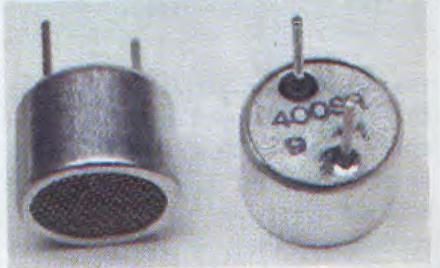
This device calculates the distance based on the speed of sound at 25o C ambient temperature and shows it on a 7-segment display. Using it, you can measure distance up to 2.5 meter. For this particular application, the required components are AT89C2051 Microcontroller, two 40KHZ ultrasonic transducers (one each for transmitter and receiver), current buffer ULN2003, operational amplifier LM324, inverter CD4049, four 7-segment displays, five transistors and some discreet components.
In this project, you excite the ultrasonic transmitter unit with a 40KHZ pulse burst and expect as echo from the object whose distance you want to measure. Fig. 1.2. shows the transmitted burst, which lasts for a period of approximately 0.5 ms. It travels to the object in the air and the echo signal is picked up by another ultrasonic transducer unit (receiver), also a 40 KHZ pre-tuned unit. The received signal, which is very weak, is amplified several times in the receiver circuit and appears somewhat as shows in Fig.1.2 when seen on a CRO.Weak echoes also occur due to the signals being directly received through the side lobes. These are ignored as the real echo receive alone would give the correct distance
Download full report here
This device calculates the distance based on the speed of sound at 25o C ambient temperature and shows it on a 7-segment display. Using it, you can measure distance up to 2.5 meter. For this particular application, the required components are AT89C2051 Microcontroller, two 40KHZ ultrasonic transducers (one each for transmitter and receiver), current buffer ULN2003, operational amplifier LM324, inverter CD4049, four 7-segment displays, five transistors and some discreet components.
In this project, you excite the ultrasonic transmitter unit with a 40KHZ pulse burst and expect as echo from the object whose distance you want to measure. Fig. 1.2. shows the transmitted burst, which lasts for a period of approximately 0.5 ms. It travels to the object in the air and the echo signal is picked up by another ultrasonic transducer unit (receiver), also a 40 KHZ pre-tuned unit. The received signal, which is very weak, is amplified several times in the receiver circuit and appears somewhat as shows in Fig.1.2 when seen on a CRO.Weak echoes also occur due to the signals being directly received through the side lobes. These are ignored as the real echo receive alone would give the correct distance
Download full report here
Monday, May 30, 2011
A circuit that allows total control over your equipments without having to move around is a revolutionary concept. Total control over the speed of the fan is a boon to many. This product brings to you this very concept. Remote control facilitates the operation of fan regulators around the home or office from a distance. It provides a system that is simple to understand and also to operate, a system that would be cheap and affordable, a reliable and easy to maintain system of remote control and durable system irrespective of usage. It adds more comfort to everyday living by removing the inconvenience of having to move around to operate a fan regulator. The system seeks to develop a system that is cost effective while not undermining the need for efficient working. The average individual these days probably picks up a remote control at least once or twice a day.
Basically, a remote control works in the following manner. A button is pressed. This completes a specific connection which produces a Morse code line signal specific to that button. The transistor amplifies the signal and sends it to the LED which translates the signal into infrared light. The sensor on the appliance detects the infrared light and reacts appropriately. The remote control’s function is to wait for the user to press a key and then translate that into infrared light signals that are received by the receiving appliance. The carrier frequency of such infrared signals is typically around 36 kHz. The aim of this work is to design and construct a remote control for a fan regulator. The remote control device sends an infra-red beam, which is received by the infra-red sensor on the regulator and the speed of the fan is increased
Download full project report here
Sunday, May 29, 2011
In today’s world security is a major concern for every society. This project is regarding the security of cars parked in the society of the accommodates. It is a hardware based security project implemented using a RFID module for a society.
Every car is mounted by a transponder(tag). When a person wants to park his car in the space reserved for the parking of a society the tag mounted on it sends a radio frequency signal. There is a receiver tag in front on the barrier of the parking area. The received signal is matched and if it does i.e. an authorized car is identified then the host computer sends a signal for the barrier to be opened automatically for the car to be parked.
The basic functionality of our project is:- The transponder or a transmitter tag is nothing but an encoder which encodes or encrypts the data to be send and there is a decoder at the other end i.e at the receiver tag accepts and matches the signal.
Download full project report in doc
Every car is mounted by a transponder(tag). When a person wants to park his car in the space reserved for the parking of a society the tag mounted on it sends a radio frequency signal. There is a receiver tag in front on the barrier of the parking area. The received signal is matched and if it does i.e. an authorized car is identified then the host computer sends a signal for the barrier to be opened automatically for the car to be parked.
The basic functionality of our project is:- The transponder or a transmitter tag is nothing but an encoder which encodes or encrypts the data to be send and there is a decoder at the other end i.e at the receiver tag accepts and matches the signal.
Download full project report in doc
Subscribe to:
Posts (Atom)